
Self-balancing robot
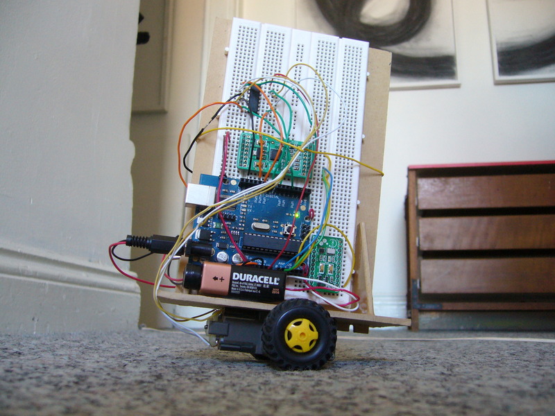
In my university days I built a self-balancing robot using an Arduino and a model truck motor kit.
Microcontroller
The all-knowing, pulsating brain of the robot is an Arduino Duemilanove microcontroller board. It was my first time using an Arduino, and it was a lot of fun.
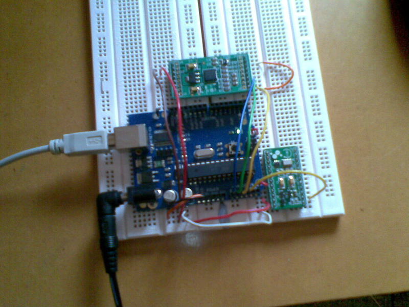
Accelerometer and gyroscope
To stay upright, the robot needs to know how much it's leaning. An accelerometer and angular rate sensor (gyroscope) need to be used together to get an accurate angle. The accelerometer gives an acceleration reading for all three axes (X, Y, Z), so simple trigonometry gives the direction of gravity, since gravity is equivalent to upward acceleration. This is highly susceptible to noise because any acceleration will interfere with the detected angle, but if it is averaged out it gives a highly accurate long-term measurement.
The gyro gives the angular rate, so if its output is integrated with respect to time, you get the change of angle. This is very accurate in the short term, but integrating the output means that small errors will accumulate to a large error and the measurement will drift. The solution is to low-pass filter the accelerometer output, high-pass filter the gyro output, and add the two together.
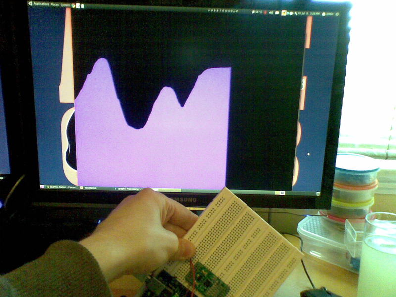
The accelerometer and gyro were from a company called Sure Electronics which seems to have disappeared in the intervening years. They're powered from the 5V supply on the Arduino and have analog outputs which are connected directly to the Arduino's analog inputs. I wrote this program to test them. It gets the angle data, processes it, and prints the angle to the serial connection to be viewed on the computer. It can also interface with this graphing program.
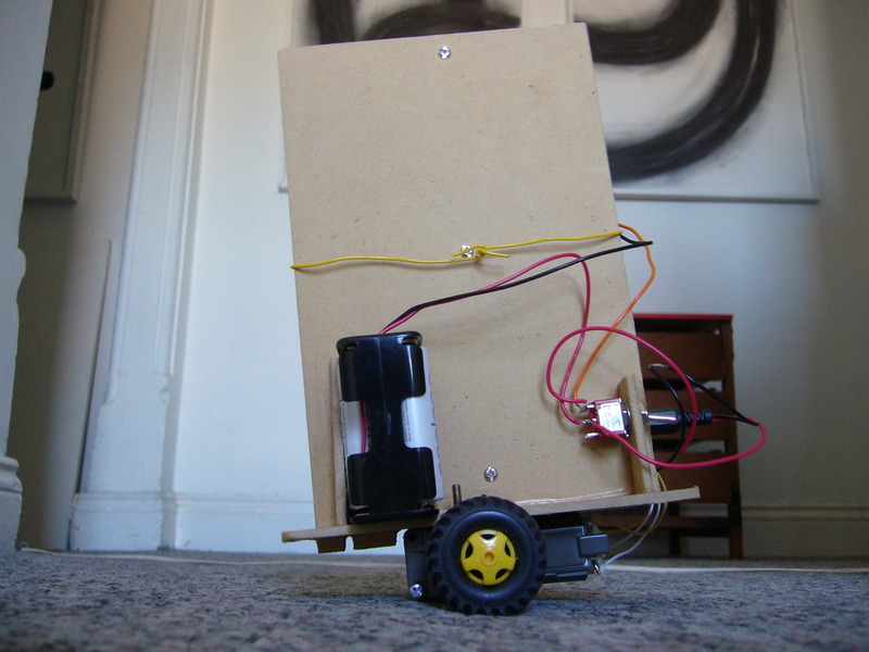
Wheels and motors
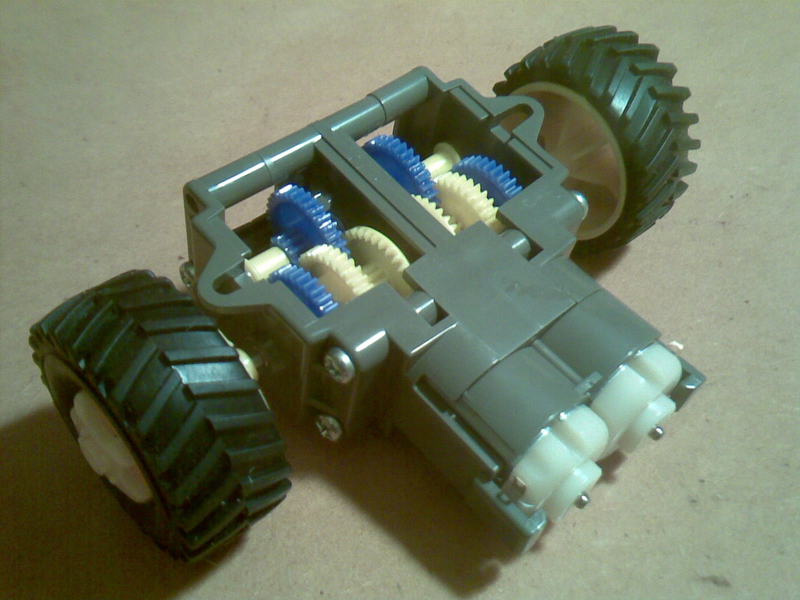
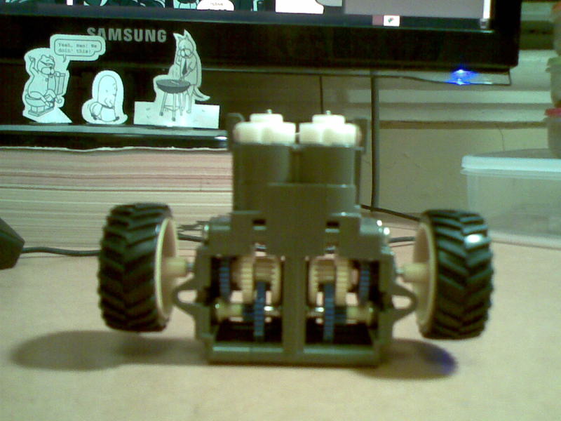
The motor/gearbox assembly is a Tamiya double gearbox kit, with 36mm Tamiya truck wheels. Originally I planned to have the gearbox positioned vertically. Unfortunately the wheels aren't big enough, and don't touch the ground with the gearbox upright, so now the gearbox is horizontal. The ground clearance isn't great, but it's enough. The main problem is restricted movement; the robot can only tip over so far until the edge of the gearbox touches the ground. But by the time it tips that far, the motors aren't powerful enough to correct it anyway.
The motors are PWM driven with an L293D driver IC which works as two H-bridges. It's rated for 600mA per channel which seems to be enough; the IC gets warm after a couple of minutes, but never hot. The motors are rated for 3V, but there's a small voltage drop in the L293D, so the voltage seen by the motors isn't quite enough for them to work well with a 3V supply. I ended up powering them with three rechargable AA batteries, with a total voltage of about 3.6V.
A standard PID controller is used by the Arduino to determine the PWM duty cycle to power the motors, with the angle as input and the duty cycle as output.
Construction
The circuitry is done on breadboard. The chassis is made from medium-density fibreboard.
Possible improvement
As it is, the robot's main problem is that it can't distinguish gravity from actual acceleration. When it starts moving to correct its tilt, the acceleration causes the reading for tilt to change and the robot slows down. This problem is reduced by the low-pass filter on the accelerometer but still causes stuttery motion. This could be fixed by putting rotary encoders on the wheels to detect the robot's acceleration, and subtract it from the accelerometer reading.
The Arduino source code is here.
Here it is in action: